 ARIA Prime Mission Electronic Equipment (PMEE)
 | ARIA Prime Mission Electronic Equipment (PMEE) |
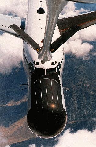
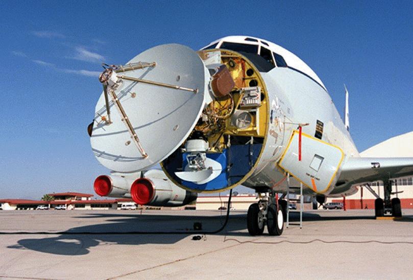
| Antenna | 7 foot parabolic dish (auto/manual track); fixed horn antenna |
| RCC/FTS | Remote Command and Control / Flight Termination System |
| DSC | Data Separation Console (bit synchs, decoms, data processing) |
| RF | Radio Frequency (receivers) |
| MC | Mission Commander |
| HF | High Frequency (communications, data relay) |
| REC | Record (magnetic tape recorders) |
| SMILS | Sonobouy Missile Impact Location System |
| Specifications | ||
| Performance Factors | EC-135 | EC-18B |
| Max Takeoff Gross Wt (lb) | 300,500 | 326,000 |
| Normal Cruise Speed (kt TAS) | 430 | 450 |
| Max Cruise Speed (kt TAS) | 490 | 470 |
| Nominal Support Speed - 30kft (kt TAS) | 360/420 | 360/420 |
| Nominal Turning Radius - 30 kft, 30 deg bank (nm) | 3.3/4.5 | 3.3/4.5 |
| Minimum Turning Radius - 30 kft, 45 deg bank (nm) | 1.9/2.6 | 1.9/2.6 |
| Nominal Turn Time, 180 deg - 30 kft, 30 deg bank (min) | 1.7/1.8 | 1.7/1.8 |
| Minimum Turn Time, 180 deg - 30 kft, 45 deg bank (min) | 1.0/1.2 | 1.0/1.2 |
| Nominal Operating Altitude (ft MSL) | 30,000 | 30,000 |
| Maximum Operating Altitude (ft MSL) | 33,000 | 42,000 |
| Mission Operating Altitude (ft MSL) | 5,000 to 33,000 | 500 to 42,000 |
| Range | The range capability of the ARIA is influenced by:
| |
| Navigation |
| |

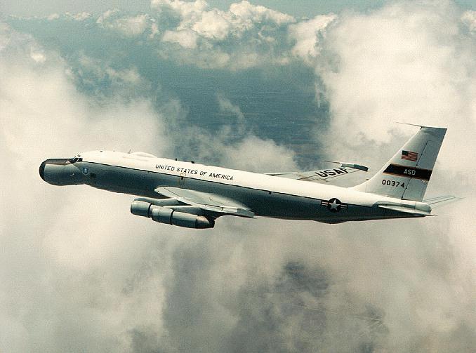
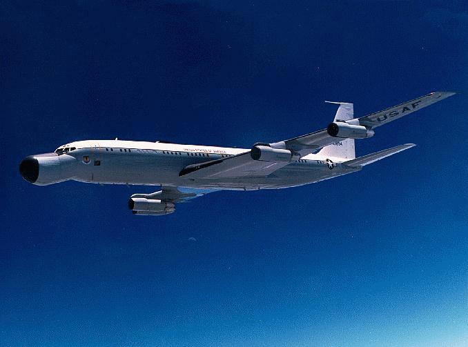
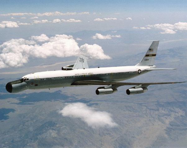
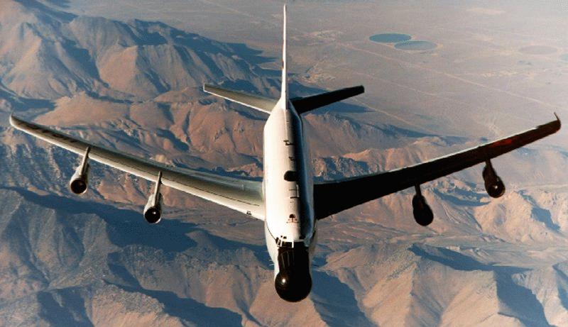
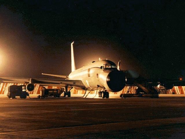
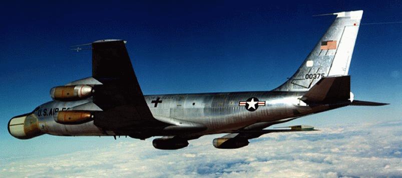
EC-18

EC-18
EC-18
EC-18
EC-18
| 歡迎光臨 鐵之狂傲 (https://gamez.com.tw/) |

